Control
Microgrids are subsystems of the distribution grid, which comprises generation capacities, storage devices, and controllable loads, operating as a single controllable system either connected or isolated from the utility grid. In this we have implemented a power flow management method for a microgrids by using model predictive control framework. In order to reliably and economically provide the required power to the costumers, the proposed method enables the microgrids to share the power generated from their renewable energy sources and minimize the power needed from the utility grid.
Model Predictive Control (MPC) utilizes a simulation model to make decisions on the amount of power that uGrid should draw from the connected maingrid, in a way that economic cost is minimized and all operational constraints are satisfied.
The MPC controller block receives 3 inputs:
1.measured output signal (mo), which would be a feedback signal from the ugrid output.
2. reference signal(ref)
3. measured disturbance signal(md)
and computes the optimal manipuated variable(mv), which would be the input to the ugrid.
Design of MPC:
In-progress Model:
Example of a Model Predictive Controller:
Adaptive Cruise Control System:
An ACC equipped vehicle (host car) has a sensor, such as radar, that measures the distance to the preceding vehicle in the same lane (lead car), as well as the relative velocity of the lead car. The ACC system operates in two modes: speed control and spacing control.
-
In speed control, the host car travels at a driver-set speed.
-
In spacing control, the host car maintains a safe distance from the lead car.
The ACC system decides which mode to use based on real-time radar measurements. For example, if the lead car is too close, the ACC system switches from speed control to spacing control. Similarly, if the lead car is further away, the ACC system switches from spacing control to speed control. In other words, the ACC system makes the host car travel at a driver-set speed as long as a safe distance is maintained.
In this example, to achieve speed control or spacing control using MPC, the ACC system manipulates acceleration.
Schematic Representation of MPC:
Based on the model, the MPC law can predict the future response of the system to various control actions[1]. At each iteration, MPC solves an optimization problem over a prediction time horizon based on current measured information of the system states, and determines the future optimal control actions[Fig1]. Only the first step of the control actions is implemented, and the rest will be ignored. The system response to this control input will be measured as the next available information for solving the optimization problem in the next iteration.
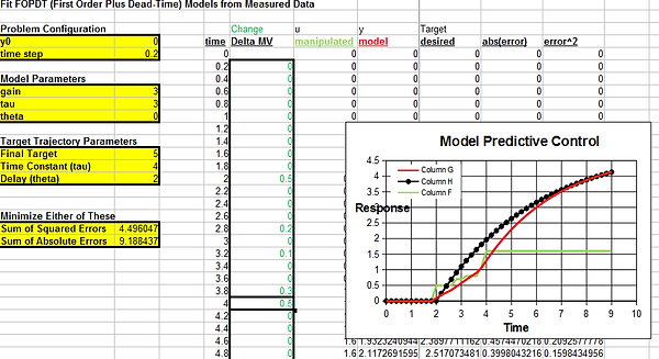
An Example to analyse MPC Controller:
This is to demonstrate , how change in delta moves , modify manipulated variable. This is turn linearize measured output. Here you can see, change in delta move in minimizing error between actual trajectory and desired trajectory.
Here, we have modified Delta mv manually to get a desired trajectory.
After updated delta mv at time = 3:
Result after updating delta" mv" at several instances:
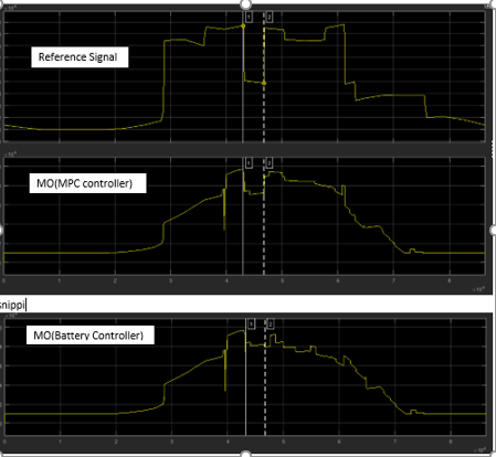
Output Scenario after running MPC design:
Above figure shows the output response of MPC when integrate with microgrid model
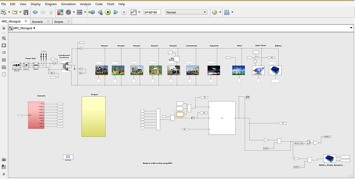
Integration of MPC with Microgrid:
Top view:
Simulation results:
Using MPC methodology we have achieved power generation trajectory, Pmo more align to the reference trajectory, but it is not true in the case where a normal battery controller were used.
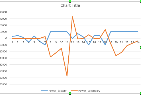
Graph of Total power in grid Vs power battery: